The six stages
CAD / DFM & split-line analysis
We read the STEP or IGES model (or scan the physical part) and check what decides cost before a tool is cut: draft angles (1–3° minimum on vertical faces), split lines and undercuts that force a multi-piece mold, ply drop-offs, core chamfers (typically 20–30°), insert and hardpoint positions, and the trim line. The output is a marked-up model and a ply book proposal.
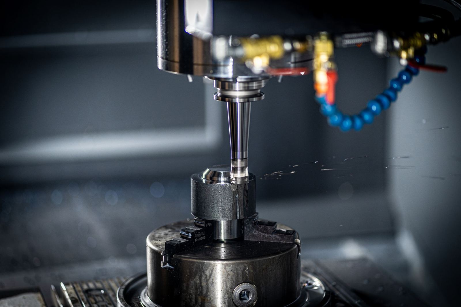
5-axis CNC pattern & tooling
Master patterns are machined from epoxy tooling board such as EB700 or high-density PU, sealed and polished. Production molds are laid up off the pattern in high-temperature tooling prepreg, or machined directly from aluminum when cycle count and tolerance justify skipping the pattern. See composite tooling & molds.
Automated kit-cutting & cleanroom layup
Ply shapes are nested and cut on a CNC ply cutter, labelled in layup order and bagged as kits. Laminators work in a temperature- and humidity-controlled layup room with debulks every few plies, core staging and film adhesive where specified.
Autoclave & oven curing
Autoclave cures run at 3–7 bar and 120–180 °C depending on the resin system, with part thermocouples and logged pressure, vacuum and temperature for every cycle. Out-of-autoclave prepregs cure in an oven under vacuum. Prepreg out-life is tracked from freezer (−18 °C) to cure. See autoclave vs OOA vs VARTM.
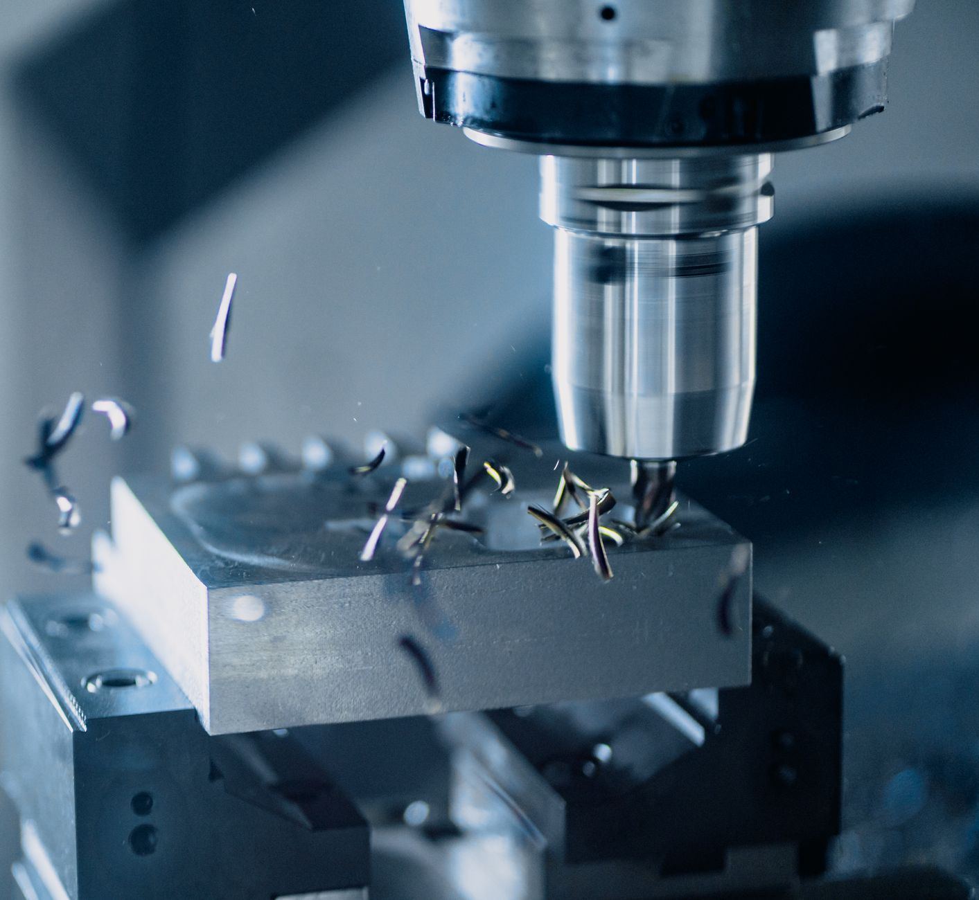
5-axis CNC trimming & bonded hardpoints
Parts are trimmed and drilled on a fixture with PCD or diamond-coated cutters under dust extraction, then titanium or aluminum inserts, brackets and threaded bushes are bonded with structural adhesive in jigs. Clear coat or paint follows if specified.
CMM / FARO metrology & ultrasonic NDT
First articles are measured against CAD with a FARO arm or CMM (typically to ±0.2 mm on trimmed edges and hardpoints) and reported. Structural parts get ultrasonic inspection: pulse-echo, phased array (PAUT) or C-scan mapping for voids and delamination.
Quality frameworks
We specify work to recognised frameworks and route it to facilities that hold the matching approvals. We do not quote certificate numbers on this site: the facility's current certificate is supplied with the quote when your program requires it.
| Framework | What it covers | When to ask for it |
|---|---|---|
| ISO 9001 | Quality management system: documented process, calibration, non-conformance handling | Baseline for any production batch |
| AS9100 Rev D | Aerospace extension of ISO 9001: configuration control, first article (AS9102), full material and process traceability | Safety-critical structures, programs with aerospace-style documentation |
| Nadcap Composites | Process-specific audit of layup, autoclave cure and bonding by PRI | When the customer requires special-process accreditation |
| FARO / CMM FAI | Dimensional report against CAD on the first article | Bolt-on aero, hardpoints, interchangeable spares |
| Ultrasonic NDT | Pulse-echo, PAUT or C-scan map of voids and delaminations | Stressed parts, repairs, crash structures |
Typical lead times
| Stage | Standard | Race-urgent |
|---|---|---|
| Tooling (pattern + mold) | 1.5–3 weeks | 5–10 days |
| First article (layup, cure, trim) | 3–7 days | 48–72 hours |
| Standard batch | 4–8 weeks | 10–14 days for small parts |
| Repair (assessment to sign-off) | 1–3 weeks | 72 hours – 10 days |
Budget the tooling and batch before you send CAD.
Open the cost estimatorDeep capability pages
Autoclave vs OOA vs VARTM
Eight-dimension process comparison and break-even by batch.
Composite tooling & molds
Pattern materials, CTE matching, split molds and the cost matrix.
Aero & bodywork
Splitters, wings, diffusers, hoods and doors: weight and cost.
NDT & crash repair
Inspection methods, scarf repair protocol and repair-vs-replace.